
- E-mail: yqkexin@gmail.com
-
Kexin Global


How to Choose and Set Up Induction Soldering Equipment
Learn how to size induction soldering equipment. Match power, operating frequency, and custom coil geometry to prevent cold solder joints and boost repeatability.
September 01, 2026
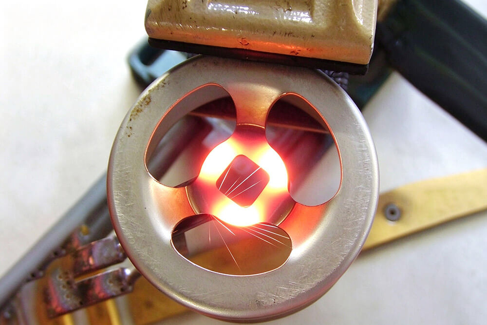
Getting a reliable solder joint requires more than simply heating the metal until the solder melts. If heat isn’t distributed evenly across the joint, the solder may not flow properly, which can lead to weak connections or problems during use.
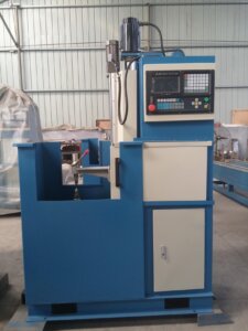
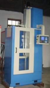
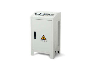
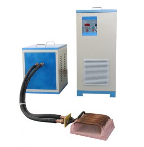
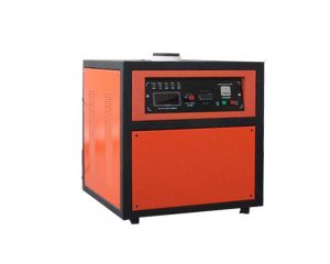
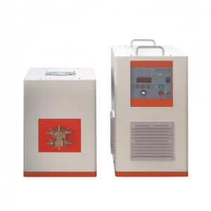
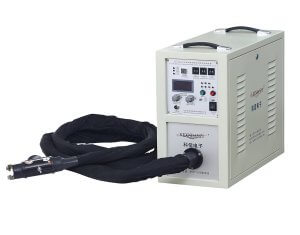
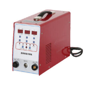
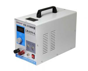
At KEXIN, we manufacture induction soldering equipment for a range of industrial applications, including copper connectors, terminals, and electrical components. Choosing the right equipment involves considering the size and material of the workpiece, the required heating temperature, and the production process. Power, operating frequency, and induction coil design all play a part in achieving consistent soldering results.
Industrial Applications of Induction Soldering
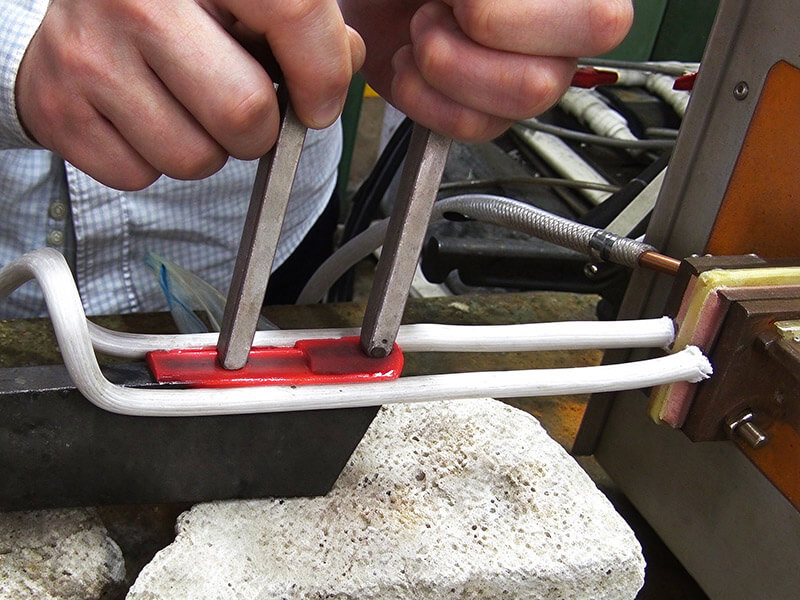
Soldering joins two metals with a filler that melts below 450 °C (840 °F), while brazing uses fillers above that line. That threshold decides which process belongs on which joint, so thin wires, cable shoes, PCB end connectors, and copper tube assemblies sit in the soldering range while thick structural joints move into brazing.
The heat source matters as much as the filler, and induction wins where the joint count is high and heat has to stay local.
| Method | Heat Source | Cycle Time | Heat Affected Zone | Repeatability |
|---|---|---|---|---|
| Soldering iron | Contact tip | Slow, operator paced | Wide on thin parts | Low to medium |
| Torch | Open flame | Fast | Very wide | Low |
| Oven or reflow | Whole assembly soak | Long ramp | Whole part | High in volume |
| Induction | Eddy currents in the joint | Seconds | Narrow, joint only | High |
With a torch, the operator controls heat by eye, while induction repeats the same power and time on every cycle, so the joint passing at nine in the morning still passes at five.
How to Set the Right Soldering Temperature
Every solder alloy has a working window, and guessing costs parts. Tin-lead eutectic melts at 183 °C, tin-silver-copper families flow near 217 °C to 220 °C, and lead-free grades sit in a similar band. You need superheat so the filler wets both surfaces, without so much that flux burns off before the joint forms.
Melting points do not set a recipe on their own. A thermocouple on a scrap part shows what the work actually reaches, and that reading is what a recipe should be built around.
Alloy choice deserves its own decision. Tin-lead stays easiest to run, tin-silver and tin-copper grades answer lead-free rules and higher service temperatures, and the flux chemistry has to suit both the alloy and the base metal.
Matching Power and Frequency to the Joint
Frequency decides how shallow the heat sits. Ultra-high frequency units run from 100 kHz to 1 MHz and concentrate energy in a thin surface layer, which suits fine wire and small connectors. High frequency covers 10 kHz to 100 kHz for mid-size parts, and medium frequency handles heavier sections at 1 kHz to 10 kHz.
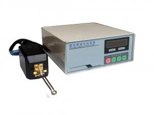
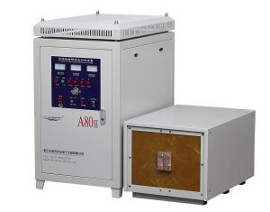
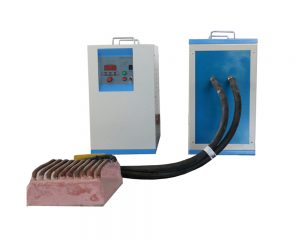
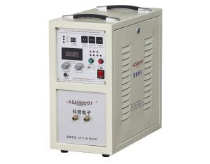
The 6KW ultra high frequency induction brazing machine we build runs at 800 kHz from a single-phase 220 V supply at 25 A, and it joins tin, silver, and copper on wire as fine as 0.1 mm. That is the class to reach for when the joint is measured in millimeters.
| Joint Type | Typical Power | Frequency Band | Notes |
|---|---|---|---|
| Wire below 0.5 mm | 3 to 6 kW | 800 kHz to 1 MHz | Short burst, low superheat |
| Cable shoe and lug | 6 to 15 kW | 100 to 400 kHz | Coil surrounds the barrel |
| Copper tube to fitting | 15 to 25 kW | 30 to 100 kHz | Split coil for access |
| PCB end connector | 3 to 10 kW | 200 kHz to 1 MHz | Shielded coil, tight control |
Those rows are starting points rather than datasheet values, because part mass, coupling distance, and coil shape shift the answer, which is why we run a sample before quoting.
Coil Geometry and Fixturing
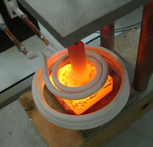
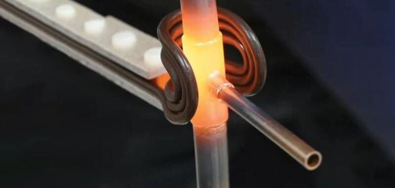
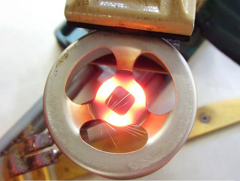
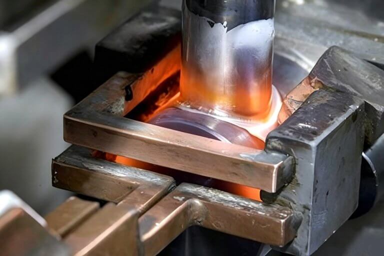
The coil is the only part of the system that touches the process, so it earns the most attention. A single turn couples tightly and heats small parts in a second or two, while a multi-turn coil spreads the field along a longer joint.
Coupling distance behaves like a volume control, since a closer coil heats faster and a wider gap spreads the heat. On repeating work, the coil should sit in a fixture so that distance never changes. Custom coils shaped to one joint do more for consistency than any tuning at the panel.
Access matters too, since a split or hairpin coil reaches joints that a closed loop cannot, which happens on tube assemblies fixed in a frame.
Process Control That Prevents Cold Joints
Cold joints come from three causes, and each has a control. The part never reached flow temperature, the filler did not wet the surface, or the joint moved while the solder solidified. Induction answers the first because heat is generated inside the metal instead of delivered from outside.
Time and power settings hold the cycle, yet position holds repeatability. Fix the coil and the part, and the heating curve stops drifting between shifts.
Temperature feedback closes the loop. A pyrometer reading the joint lets the controller stop on temperature rather than on time, which matters when incoming parts vary in mass. On sensitive assemblies, a shielding gas keeps the surface clean enough to wet without aggressive flux. Where a part needs a brazed joint instead of a soldered one, the physics changes.
Common Defects and Their Causes
| Defect | Likely Cause | Correction |
|---|---|---|
| Cold joint, dull surface | Too little power or short cycle | Raise power or extend time, verify with thermocouple |
| Solder ball, no wetting | Surface contamination or weak flux | Clean parts, review flux and atmosphere |
| Burned flux residue | Excessive superheat | Lower power, shorten cycle |
| Cracked joint after cooling | Part movement during solidification | Add fixture support, hold position until set |
| Uneven joint along a tube | Coil not centered on the joint | Recenter coil, check coupling distance |
Looking at soldering defects across a production batch can help identify problems with the heating process. If similar defects keep appearing, it’s worth checking the induction coil position, fixture alignment, and heating settings before making further adjustments. Coil design and operating frequency also affect how heat is distributed across the joint.
Frequently Asked Questions
How is induction soldering different from induction brazing?
The filler melting point separates them. Soldering stays below 450 °C (840 °F) and brazing runs above, so brazed joints carry more load while soldered joints suit thin sections and heat-sensitive assemblies.
What temperature range should I target?
Match the alloy with a margin for wetting. Tin-lead eutectic works near 183 °C and tin-silver-copper near 220 °C, and the joint needs enough superheat to flow without burning flux.
Which solders work with induction heating?
Tin-lead, tin-silver, and tin-copper alloys all run well, and lead-free grades are common where rules require them. The filler has to suit the base metals and the service temperature.
Can induction soldering run in an automated line?
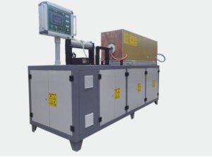
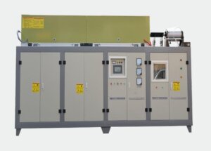
Yes, because the cycle is electrical and a PLC can trigger the power supply, hold the recipe, and index the part. Repeatability is why most high-volume soldering moves to induction.
How do I choose the right machine?
Start with the joint rather than the catalog. Measure the wire or lug, decide the alloy, then pick a power and frequency band that heats that mass inside your cycle time.
Conclusion
A reliable induction soldering process depends on getting the heating conditions right for the joint. Solder alloy, joint dimensions, coil position, and temperature all affect the final result. Running a few sample parts and checking the solder flow before starting production can help identify problems early.
At KEXIN, we manufacture induction soldering and brazing equipment, ranging from 6 kW handheld units to automated systems. We can also test customer samples to help determine suitable heating settings. You can browse our induction soldering equipment or find out more about our coil design service if your application needs a custom coil. If you have specific project parameters, feel free to contact KEXIN for tailored recommendations.
Related Articles
Explore News >
Request A Quote
Can't find the answer you need? Tell us about your application and our engineers will get back to you.