 Whatsapp
Induction Coil Design Guide
Induction heating performance depends on many factors, but coil design is one of the most influential and often the most overlooked. The geometry, material, and positioning of a coil can directly affect heating consistency, cycle time, and overall system efficiency.
A well-designed induction coil helps ensure uniform heat distribution, reliable process control, and repeatable results on the production floor. Poor coil design, on the other hand, can lead to uneven heating, higher energy consumption, and increased wear on both parts and equipment.
This article reviews the fundamental principles of induction coil design and shares five practical tips to help engineers and manufacturers optimize coil performance for specific parts and processes.
How Induction Heating Coils Work?
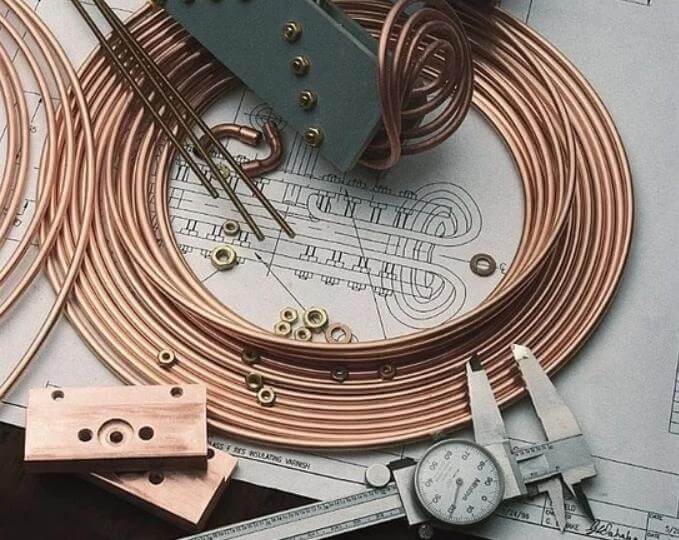
The induction coil determines how effectively and efficiently a workpiece is heated. Induction coils are water-cooled conductors made of copper tubing that is readily formed into the shape of the coil for the induction heating process. Induction heating coils do not themselves get hot as water flows through them.
Work coils range in complexity from a simple helical- or solenoid-wound coil (consisting of a number of turns of copper tube wound around a mandrel) to a coil that is precision machined from solid copper and brazed.
Coils transfer energy from the power supply to the workpiece by generating an alternating electromagnetic field due to the alternating current flowing in them. The coil’s alternating electromagnetic field (EMF) generates an induced current (eddy current) in the workpiece, which generates heat due to I Squared R losses (core losses).
The current in the workpiece is proportional to the coil’s EMF strength. This transfer of energy is known as the transformer effect or eddy current effect.
How to Design the Right Induction Coil?
The design of an induction coil has a significant impact on process efficiency and final part quality, and the best coil design for your product largely depends on your application. Certain coil designs tend to perform optimally in specific applications, while an inappropriate coil and application can lead to slow or uneven heating, increased defect rates, and decreased product quality.
Designing an Induction Coil for Your Application
First, understand the location within the part where heat needs to be generated to complete the machining process, and then design the coil to achieve the desired heating effect. Similarly, the choice of frequency depends on the induction heating application you will be using for the part.
Before designing an induction coil, consider the following three factors and your induction application:
Part Movement Relative to the Coil: Many applications rely on moving parts using conveyors, turntables, or robots. A well-designed induction coil can meet these different operational requirements without sacrificing heating efficiency.
Frequency: Applications requiring surface heating, such as brazing, soldering, annealing, or heat treatment, typically use higher frequencies. Applications requiring internal heating to the core, such as forging and die heating, tend to use lower frequencies.
Power Density Requirements: High power density is required for short-cycle heating applications that demand high temperatures. In addition, higher power density may be required to confine the hot zone to a smaller area and thus reduce the heat-affected zone.
Types of Induction Coils
Induction heating employs a variety of coils with distinct heating behaviors and applications. Let’s explore some common types of induction coils:
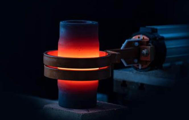
Single-Turn Coil
Also known as a solid inductor, the single-turn coil eats the workpiece along a narow band and can scan the length of the workpiece
Internal Coil
This coil is uniquely designed to heat the inner surfaces of holes, reducing the distance from the holes’ surfaces to optimize heat distribution.
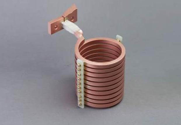
Multi-Position Helical Coil
Ideal for comprehensive heating processes, this coil can be configured into multiple positions, typically accommodating up to eight positions.
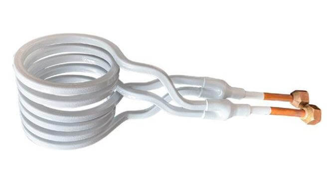
Hairpin Coil
Available as single or multiple-turn coils, hairpin coils are employed to heat long and thin parts,as well as moving steel or aluminum.
Now that we’ve explored various coil types, let’s delve into the basics of induction heating coil design
Pancake Coil
It’s used to heat a workpiece from one side only, particularly suitable for flat-surfaced metals. lt heats a small arrow band from the center.
Curved Channel Coil
Utilized on rotary tables, these coils facilitate a step in the multistep assembly process.
Five Conditions to Note
1. The higher the magnetic flux density near the heating area, the greater the current generated in the workpiece.
The coil should be placed as close to the workpiece as possible to maximize the intersection of magnetic lines of force with the workpiece at the heating point. This achieves maximum energy transfer.
2. The region with the most magnetic lines of force in a solenoid coil is located near the center of the coil.
The concentration of magnetic lines of force inside the coil maximizes the heating rate at this location.
3. The geometric center of the coil is a region of weaker magnetic flux.
Magnetic flux is most concentrated near the number of turns of the coil and decreases with increasing distance from the number of turns.
If the workpiece is placed off-center from the coil, the region near the number of turns will intersect with more magnetic lines of force, resulting in a higher heating rate.
Regions further from the copper coil have weaker coupling and a lower heating rate. This effect is more pronounced in high-frequency induction heating.
4. The magnetic center of the inductor is not necessarily its geometric center. The magnetic field is weaker at the connection between the leads and the coil.
This effect is most pronounced in single-turn coils. As the number of turns increases, the magnetic flux of each turn is superimposed on the flux of the previous turn, thus gradually reducing the effect.
Since it is impractical to always place the workpiece at the center of the working coil, in static heating applications, the workpiece should be slightly offset towards this area. If possible, the workpiece should be rotated to ensure uniform heating.
5. The coil design must prevent magnetic fields from canceling each other out.
If the inductors are positioned too close together, the coil’s inductance will be insufficient for effective heating. Placing a loop at the center of the coil can cancel this effect. This allows the coil to heat the conductive material inserted into the loop opening.
Induction Coil Installation
Proper installation of the induction coil is as critical as its design. Incorrect installation can lead to significant downtime. It’s advisable to follow the manufacturer’s manual for coil installation or replacement.
When replacing the coil on an induction heating device, keep the following points in mind
- Ensure the main switch and cooling water are turned off.
- Place a container beneath the inductor to catch any leaking cooling water.
- Loosen the nuts on the connector jaws to release the thrust parts carefully.
- Remove the old coil and install the new one.
- Ensure a tight fit between the coil and the coaxial transformers.
Note: Always use brass nuts and washers.
FAQ
Q Will I get an electric shock if I touch the induction coil during operation?
The coil is a live component and is therefore prone to high-frequency short circuits. Therefore, we recommend avoiding any physical contact with the coil while it is in operation. Always take adequate precautions to prevent others from touching the coil.
Q What precautions should operators take when handling live coils?
Operators should wear gloves with an appropriate voltage rating when working on exposed copper coils. A non-metallic shield can also be placed between the coil and the operator to prevent accidental contact.
Q How long do induction coils last?
Following proper usage, a single coil should last between 200-300 uses. Replace coils if you notice fraying, discoloration, or reduced efficiency. Using damaged induction heating coils can be extremely dangerous. Heating metal on metal can risk arcing and burning the unit out.
Q Is a coil an inductor or capacitor?
In fact, the inductor is basically a coil of wire. Ampere’s Law: current in a coil → magnetic field Faraday’s Law: Time-varying magnetic field → induced voltage (emf) In circuits that we will study, the time-varying magnetic field is produced by a changing current.
Q Does an induction coil get hot?
Induction coils are water-cooled copper conductors made of tubing that is formed into the shape of the coil for the induction heating process. Induction heating coils do not themselves get hot as water flows through them.
Q How to power an induction coil?
To power up your induction heater, just connect it to the power supply you have. Then, insert the part you are trying to heat up into the coil. It should start heating.
KEXIN’s induction melting furnace has higher thermal efficiency and lower energy consumption. They can produce a mild metal bath mixture, mixing a uniform alloy at a constant and uniform temperature. For these reasons, this type of furnace is the first choice for induction melting. Kexin products can flexibly meet all customer requirements.
Can we help you?