 Whatsapp
Engineering Design of Induction Heating Quenching Furnaces
Induction hardening furnaces are central to many modern heat treatment processes. They combine rapid, precise heating with controlled, rapid cooling to achieve specific hardness distributions and mechanical properties in metal parts.
To effectively design these systems, engineers need not only to understand the relevant electromagnetic and thermal principles but also the interactions of power, frequency, coil geometry, and hardening conditions in a real-world production environment.
From a macroscopic perspective, induction heating relies on electromagnetic induction to generate eddy currents and hysteresis losses within a conductive workpiece. These internal losses efficiently convert electrical energy into heat.
The hardening process rapidly removes this heat, forming a martensitic structure that produces a hard, wear-resistant surface. The design challenge lies in shaping, controlling, and repeating this process to ensure seamless integration between parts.
Fundamentals of Induction Heating and Quenching
Metals can be heated without direct contact, simply by placing them in a time-varying magnetic field. According to Faraday’s law of electromagnetic induction, an alternating magnetic field induces eddy currents near the surface of a conductive workpiece.
These eddy currents flow through the material’s resistance, generating heat (Joule heating). For ferromagnetic materials like steel, the continuous magnetization and demagnetization of magnetic domains also generates additional heat due to hysteresis losses.
A basic induction heating system consists of three main components:
- An induction coil: typically a copper tube shaped to match the geometry of the workpiece.
- An AC power source provides controllable voltage, current, frequency, and power.
- The workpiece: the metal part to be heated and subsequently hardened.
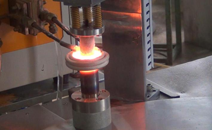
When a steel part is placed inside or near the induction coil and energized, its surface can turn red, orange, or even yellow within seconds, requiring no physical contact.
This rapid, localized heating method is ideal for surface hardening, requiring only a specific depth of hardened layer while the core retains its toughness and ductility.
Induction heating is widely used in various heat treatment processes:
- Surface (carburizing) hardening and overall hardening
- Annealing and normalizing
- Tempering and stress relief
- Bragging, welding, and forming
While many metals can be induction heated, such as steel, cast iron, copper, aluminum, brass, bronze, etc., induction hardening of steel parts is by far the most common application, with surface hardening being the primary use.

Frequency and Power in Induction Heat Treatment
Once the basic principles are understood, the next critical step in furnace design is selecting appropriate frequency and power. These parameters strongly influence heating depth, speed, uniformity, and overall hardening quality.
Frequency Selection and Heating Depth
The frequency of an alternating current (AC) circuit determines the penetration depth of the induced current within the workpiece; this phenomenon is commonly referred to as “skin depth.”
Simply put:
- Higher frequency ⇒ Shallower penetration
- Lower frequency ⇒ Deeper penetration
For surface hardening applications, the goal is to concentrate heat in a controlled hardened layer beneath the surface to achieve the desired hardened layer depth. If the frequency is too high, the hardened layer may be too shallow or uneven. If the frequency is too low, too much of the cross-section may be heated, leading to over-deformation or overall hardening, when only a hardened layer is needed.
Therefore, the choice of frequency must be closely related to the following factors:
- Material grade and magnetic properties
- Part geometry and wall thickness
- Target hardened layer depth and profile
- Production efficiency and energy efficiency targets
Power Density and Maximum Quenching Area
Besides frequency, power density also controls the rate at which the surface reaches its austenitizing temperature. At a given frequency:
- Higher power density ⇒ Faster heating rate
- Lower power density ⇒ Slower heating rate and a more gradual process
The goal of surface hardening is to rapidly heat the surface to achieve austenitization without overheating. When the power density is properly matched, the part will form a clear hardened layer with minimal thermal damage.
However, excessive power or improper tuning can lead to surface scorching, uneven hardening, or excessive residual stress.
The maximum quenching area that can be processed at one time also depends on the available power, coil design, and coolant delivery system.
The furnace design must consider both the required electrical capacity and mechanical structure to ensure consistent processing throughout the entire processing area.
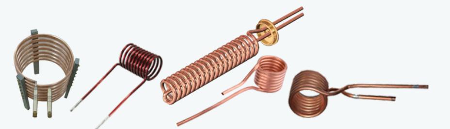
Coil Design and Uniformity of Heating
Induction hardening inductors are key heating elements that utilize the eddy current principle to perform surface hardening and strengthening of parts. Since there are many types and shapes of parts requiring surface heating, the design of inductors varies accordingly.
Typically, the dimensions of an inductor mainly depend on the diameter, height, cross-sectional shape of the induction coil, the cooling water path, and the nozzle.
1. Induction Coil Diameter
The shape of the induction coil depends on the surface profile of the part being heated. A certain gap must be maintained between the induction coil and the part, and the profiles of all parts should be consistent.
- When heating the outer diameter, the inner diameter of the induction coil is D = D0 + 2a;
- When heating the inner diameter, the outer diameter of the induction coil is D = D0 – 2a.
- Where D0 is the outer or inner diameter of the workpiece, and a is the gap between them.
- For shaft parts, the gap is 1.5~3.5mm, for gear parts, the gap is 1.5~4.5mm.
- For internal bore parts, the gap is 1~2mm. If medium-frequency heating and quenching processes are used, the gap will be slightly different.
- Typically, the gap for axial parts is 2.5~3mm, and the gap for internal bore parts is 2~3mm.
2. Induction Coil Height
The height of the induction coil mainly depends on the power setting P0 of the heating equipment, the workpiece diameter D, and the set specific power P:
- For the primary heating of short shaft parts, to prevent overheating of sharp corners, the height of the induction coil should be less than the height of the part.
- For primary heating and localized cooling of long-shaft parts, the height of the induction coil should be 1.05 to 1.2 times the length of the cooling zone.
- Excessive height of a single-turn induction coil can lead to uneven heating of the workpiece surface, with the temperature in the middle being much higher than the temperatures on the sides. This phenomenon is more pronounced at higher frequencies. Therefore, double-turn or multi-turn induction coils are usually used.
3. Cross-sectional Shape of Induction Coil
Induction coils come in various cross-sectional shapes, such as circular, square, rectangular, and plate-shaped. With the same quenching area, bending the induction coil into a rectangular cross-section is more economical and produces a more uniform heat-conducting layer.
A circular cross-section has poorer heat conductivity but is easier to bend. The materials used are mostly brass or copper tubing. The wall thickness of high-frequency induction coils is 0.5mm, and that of medium-frequency induction coils is 1.5mm.
4. Cooling Water Circuit and Spray Nozzles
Considering the heat generated by eddy current losses, all components require water cooling. Copper pipes can be directly cooled with water. Copper plate components can be stacked or welded to copper pipes to form a cooling water circuit.
For high-frequency continuous or synchronous heating using self-spraying cooling, the induction coil nozzle diameter is 0.8~1.0mm. For medium-frequency heating, it is 1~2mm.
During continuous heating and quenching, the induction coil nozzle angle is 35°~45°, and the nozzle spacing is 3~5mm. Simultaneously, the heating and quenching nozzles should be staggered with uniform spacing.
Generally, the total nozzle area should be smaller than the inlet pipe area to ensure that the spray pressure and inlet water pressure meet requirements.
It is worth noting that to address the ring effect generated by internal heating, iron oxide or silicon steel sheets can be sandwiched on the induction coil to form a grid-like magnet, allowing current to flow along the gaps between the magnets. To prevent overheating of hardened components, a magnetic short-circuit shielding ring can be made using a steel ring or soft magnetic material.
Furthermore, during induction heating, the gap near the sharp corners of the induction coil should be appropriately increased to prevent localized overheating.
The Applications of Induction Heating Quenching Furnaces
Induction heating quenching furnaces are widely used for directional heating, applying heat only where it is needed.
Key application areas include:
- Surface hardening of gears, shafts, bearings, and other wear components
- Through hardening of certain parts with specific cross-sections
- Melting and casting in induction furnaces
- Brazing and welding of joints and assemblies
- Hot forming, such as forging and extrusion preheating
Although iron and steel are ideal candidates due to their ferromagnetic properties and phase transformation behavior, induction heating can also be applied to many other conductive materials. Eddy currents can be induced in any conductor, and hysteresis heating occurs in any magnetic material.
In some industries, induction is used to heat graphite crucibles and to process semiconductor materials like silicon. Power-frequency (50/60 Hz) induction systems are common in cost-sensitive applications, as they can be driven directly from the grid without complex high-frequency inverters.
By adjusting coil design, frequency, and power density, the same fundamental technology can be adapted to everything from small precision components to large industrial parts, and from shallow case hardening to bulk melting.
Conclusion
The engineering design of induction hardening furnaces is far more complex than simply selecting a power source and winding coils around a workpiece. It is a comprehensive systems engineering challenge.
Electromagnetic characteristics, thermal response, mechanical integrity, hardening kinetics, control strategies, safety, and lifecycle costs all interact.
When these elements are designed holistically, induction hardening offers not only precise control but also high repeatability and efficiency.
Modern factories increasingly rely on advanced process controls to maximize the performance of induction systems.
Closed-loop monitoring of power, frequency, workpiece temperature, and hardening conditions reduces scrap rates and operator dependence while meeting stringent metallurgical specifications.
These controls also provide process traceability, crucial in demanding industries such as automotive and aerospace.
Ultimately, a well-designed induction hardening furnace is more than just a heat treatment tool; it is a strategic asset.
By combining electromagnetic design, coil engineering, and process control with the actual needs of production, manufacturers can achieve consistent hardness, higher throughput, and better energy efficiency, gaining a significant competitive advantage in modern manufacturing.
KEXIN’s induction melting furnace has higher thermal efficiency and lower energy consumption. They can produce a mild metal bath mixture, mixing a uniform alloy at a constant and uniform temperature. For these reasons, this type of furnace is the first choice for induction melting. Kexin products can flexibly meet all customer requirements.
Can we help you?